draw a circle in 3d sketch inventor
Inventor Sketching: Beyond the Basics
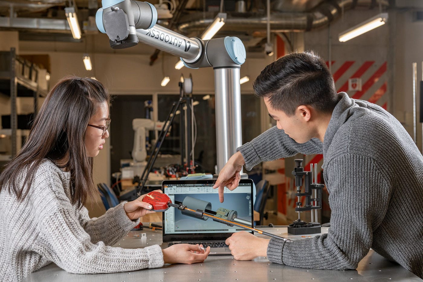
By Mike Thomas for Autodesk University
Sketching is the basis of whatsoever model. In this article, nosotros'll explore sketching within Inventor software, including how to build a stone-solid foundation for your models and time-saving tips and tricks to brand you lot more than productive.
Sketching
Sketching is the foundation for most of the components modeled. So it is important to take stiff sketching skills. Near 3D models outset from a sketch, and are then farther defined through sketched and placed features. Sketches contain 2D or 3D objects. Use the Inventor Sketch environment to sketch, constrain, and dimension 2D geometry.
I've learned many tips and tricks from my many years of using Inventor, both from using the software and from watching and learning from other users. "It's not what you know, information technology's who you know," every bit the saying goes, but it's really both. I am always on the picket for any steps that reduce the time to get things done or that will build stronger, amend models. Then, here are some of my favorites.
From Inventor:
Part models created in Autodesk Inventor outset with sketches, which you create past drawing geometric elements such as points, lines, shapes, and arcs. The sketch becomes the basis for sketched features, such as extrusions, revolutions, lofts, coils, or sweeps, which add volume to the sketched role. When starting a sketch, you tin specify a planar face, work plane, or sketch bend. A sketch contour is a closed loop defined by sketched or reference geometry that represents a cross-section of a feature. An open up profile divers past sketched segments, arcs, or splines can define a surface shape or extend to boundaries to close a region.
Related — Taking Information technology to the Next Level: Cartoon Automation with Autodesk Inventor with Thomas Fitzgerald
Getting Your Sketch Started
Using Sketches to Define Work Features
Start Workplanes while Sketching — Generate an first workplane with a sketch in one step by dragging off the desired face up with the Create Sketch command agile.
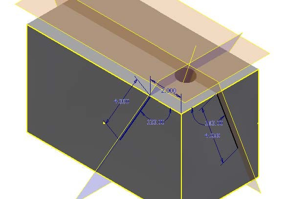
Use Sketches to Define Work Features
Sketch geometry, especially lines, tin provide an easier method for creating work features that are difficult to locate.
Slice Graphics
When the model is in the style, utilise Piece Graphics to remove everything between you and the sketch plane.
Initiate Piece Graphics via:
- the correct-click menu
- by pressing F7
- the pick in the Status bar
Tip: If sliced in the incorrect direction, turn off the slice graphics, rotate the model, and endeavor slice graphics again.
Copying and Pasting
Using the Windows Clipboard, create copies of sketch geometry pasted into the same sketch, into the aforementioned model, or even between parts. Employ the standard Microsoft Windows functions (right click Copy or <Ctrl> + C and right click Paste or <Ctrl> + V).
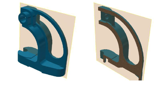
Projection Geometry
Use Project Cut Edges to associate project edges of the model that intersect with the sketching plane. Recollect of it as the edges of a department view and your sketch is the section line.
Project Flat Pattern unfolds a disjointed confront or faces into the sketch plane.
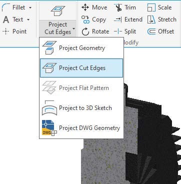
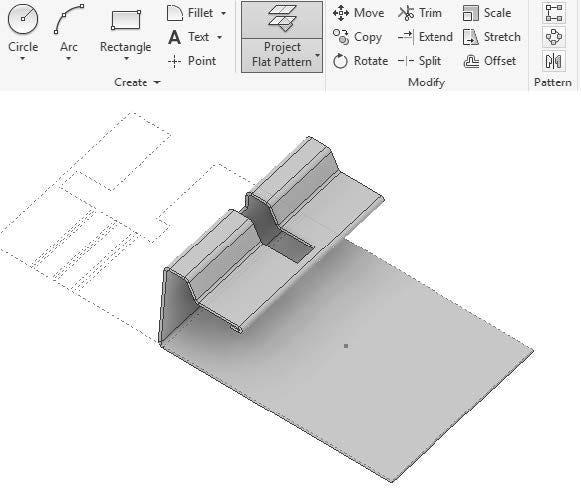
Tip: Project Apartment Pattern is great for the situations where yous do not crave the overhead and advanced options of the Canvass Metal Unfold / Refold features. It is for when you just want to reference existing geometry edges.
Want to share your cognition?
Write an article for AU
AutoCAD Geometry
Importing AutoCAD Geometry — Why redo when you can reuse? AutoCAD geometry can be imported into your sketches. Once it is imported, add together dimensions and constraints equally if the geometry originated in Inventor.
Tip: You tin copy and paste direct from AutoCAD into Inventor to featherbed the sorcerer.
With the geometry imported, use Auto Dimensioning to apply the "easy" constraints similar horizontal, vertical, perpendicular, and parallel.
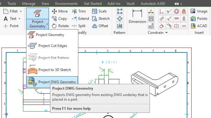
Use AnyCAD to associatively import AutoCAD drawings into your Inventor model. And then, from inside a sketch, use Project DWG Geometry to project in reference objects from the AutoCAD drawing. If the AutoCAD drawing changes, this projected geometry automatically updates.
Make Project Geometry Work for You
Past default, projecting geometry from ane office into another is made adaptive and remains linked to the original component. While information technology is adaptive (and associated) you cannot make changes to the projection geometry as it is locked so that it updates as the other component changes.
Override this behavior past pressing CTRL while yous are projecting geometry. The geometry projects fixed in identify, merely not adaptive. When geometry is projected from another component (not adaptively) Inventor applies fix constraints to ground the geometry in place.
Adaptivity has its pros and cons. It is a very powerful tool when you intend to apply information technology. Unfortunately, the default beliefs makes it also piece of cake to accidentally or inadvertently invoke adaptive.
In the Awarding Options (Associates Tab), disable the cross function geometry projection settings to reverse the default behavior. With these options disabled, yous'll have to hold CTRL when projecting geometry to make information technology adaptive.
Tip: Quickly remove Fix Constraints by selecting the geometry, correct clicking, and selecting Remove Ready Constraints. This will remove all fix constraints on the selected geometry.
Creating Geometry
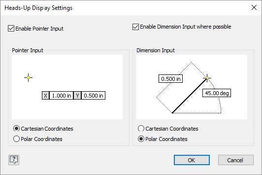
Utilizing Dynamic Input
Dynamic Input, originally introduced in AutoCAD, is a method of working with sketch geometry. It provides a Heads-Up Brandish (HUD) near the cursor, keeping your focus on the chore at hand.
Input boxes will announced every bit you lot are creating 2d geometry showing transitional dimensional information about your geometry and information technology allows yous to ascertain the size of the object as you lot are creating it, even creating the dimension.
Tip: A key to working with Dynamic Input is the Tab primal toggles between the various options, whereas Enter will accept the sizes.
Values entered become dimensions when accepted. Dimensions are only created on the inputs you entered a value for.
Configure Heads-Up Display (HUD) within the Application Options (Sketch tab).
Just Similar AutoCAD
In many means, Inventor mimics AutoCAD, providing little time savers (see a few below). Whether large or small, what saves time is a good thing.
- The Spacebar repeats the last command
- When drawing a line, right click and shut the line
- Switch between arcs and lines in the aforementioned command
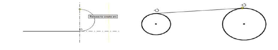
Cartoon Lines
When sketching lines employ the printing-and-hold options to generate constrained lines or switch into a tangent arc creation mode.
If you press-hold-and-drag off any point, Inventor generates a tangent arc from that point. If you printing-hold-and-drag away from a line or arc, Inventor creates perpendicular lines.
If you press-concur-and-drag tangent-like from an arc or circle you create a tangent line. If you go on to printing-and-concur as you lot create the line, you tin snap tangent at the other end as well.
Drawing Rectangles and Slots
Inventor provides multiple methods for creating rectangles and slots. Opposed to using lines and arcs, use the advisable option. With both rectangles and slots, select the pick that provides the easiest (and best) method for locating the shape and reduces the steps to create the shape.
Cartoon Splines
Inventor provides multiple methods for generating Splines.
Utilise specific equations to define Equation Curves.
Interpolation splines laissez passer through a series of points called fit points. You modify the curve using handles on the points. Each fit indicate when selected provides handles, used to modify the curvature of the spline.
The Control Frame defines Control Vertex splines. Control vertices on the frame influence the spline curves. The spline is tangent to the control frame at the start and end points. To constrain and modify the spline, work with the ends of the control frames.
Tip: The right-click bill of fare provides options to insert additional vertices and to convert the spline to the interpolation type.
Offsetting
Offset creates geometry by offsetting existing feature edges. Just like AutoCAD, zero-length segments are automatically removed by the offset process.
Tip: You lot practice not demand to offset the entire loop; instead, disable Loop Select from the right-click card.
Using Split up
Use Split to divide entities into two or more objects. When geometry is broken autonomously using Carve up, the geometry remains constrained, pregnant it is a not bad method to generate construction geometry or to create points to snap to.
Adding Text to Your Sketches
Add text to any sketch and and so emboss or extrude the objects to add features to your model. Apply this to generate features like part numbers, dates, identify of industry, brand names, and logos stamped, engraved, or etched into the component.
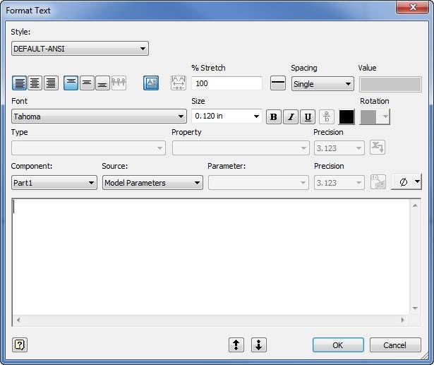
Sketched text tin can include model parameters, meaning that as the parameters update and so does the text. The location of the text can be parametrically positioned either by the insertion signal or the text box can be enabled providing more fine-tuned positioning.
Geometry Text functions in a similar way simply will adapt the text to a selected object — for example, wrapping the text to an arc.
Using Sketches and Sketch Points to Build Hole Patterns
Any point in the sketch can be used every bit a hole centre (not just hole centers). Quickly alter points to hole centers by selecting the points and adjusting their format. There are many opportunities to employ rectangles, polygons, and / or offset to create the hole design base more than hands and smarter compared to patterning.
Export Face and Export Apartment Design
Any face up or whatsoever flat pattern tin exist exported to DWG or DXF, avoiding the demand for a cartoon.
Explaining the Options with Move, Copy, Scale, Rotate, and Stretch
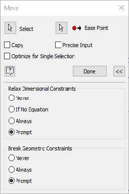
Move, Re-create, Scale, Rotate, and Stretch all provide an expanded portion to the dialogs. Utilize these to define how to handle constrained geometry.
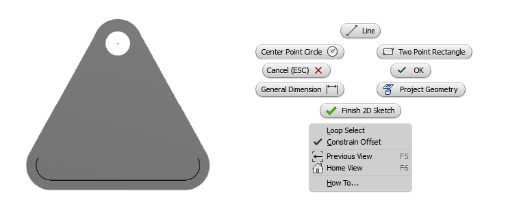
Take, for instance, the following sketch. The circle is fully constrained from the 0.75 dimension and a vertical constrain between the center of the circle and the midpoint of the edge of the rectangle.
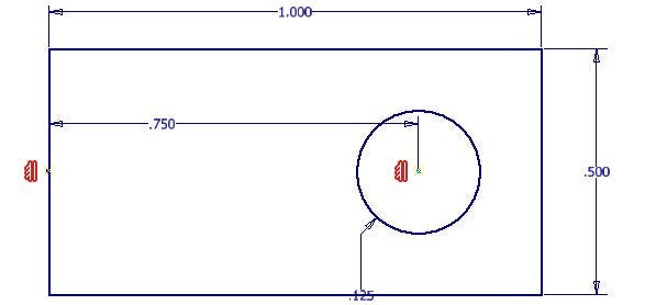
When attempting to move the circle, Inventor prompts regarding the applied dimensions. If the dimension is not relaxed, you lot will be unable to move the circumvolve left or right inside the sketch.
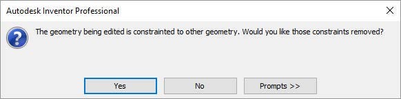
Adjacent, Inventor prompts to delete the applied constraints. In this example, past not removing the vertical constraint y'all cannot move the circle upward or downwards within the sketch.
Apply the expanded portion of each dialog to ascertain the prompting. Select Prompt to exist prompted each time using ane of these commands. Select Never to not be prompted, and to never remove constraints nor relax dimensions. Select Always to non be prompted, simply to always remove the constraints and e'er relax the dimensions.
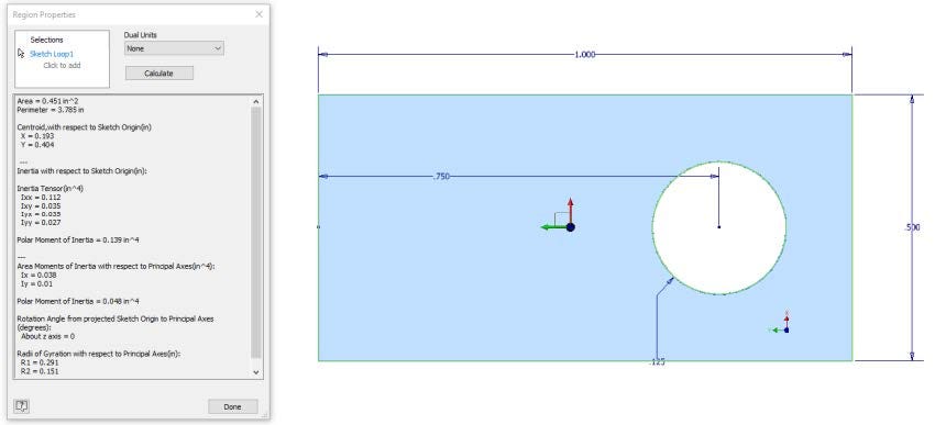
Region Properties
Region Properties is a sketch-just tool. After selecting the desired areas to include, select Calculate. Inventor provides the Area, Perimeter, Centroid, and other mechanical properties.
Offsetting
Offset creates geometry by offsetting existing feature edges. As a bonus tip, you do not need to select the unabridged loop if you disable the Loop Select choice on the correct-click menu.
Just like AutoCAD, nil-length segments are automatically removed by the offset procedure.
Sketch Options
The Awarding Options contain options specific for sketches.
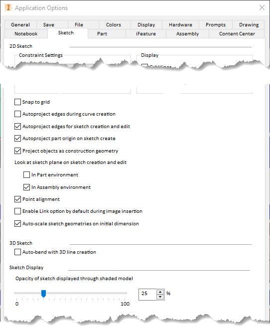
Projecting Options
- Autoproject edges during curve cosmos — Projection edges and other sketch geometry by hovering over and "rubbing" the object.
- Autoproject edges for sketch creation and edit — Auto-project the edges of the selected face onto the sketch plane every bit reference geometry.
- Autoproject part origin on sketch create — Automatically project the models origin point every bit reference geometry (this is a must!).
- Project objects as construction geometry — Project all geometry as construction geometry.
Look At
- Look at sketch plane on sketch creation and edit — When enabled, entering sketch mode automatically reorients the graphics window so that the sketch plane is parallel to the view.
Point Alignment
- Point alignment — Enable to infer alignment between endpoints of newly created geometry. If disabled, you must laissez passer the cursor over the points in the sketch to invoke. (Annotation that this does not create constraints.)
Sketch Opacity
- Sketch Display Opacity — Manages the corporeality the sketch is visible through the shaded model. 0% = sketch is opaque — blocked past model.
Using Sketches and Sketch Points to Build Hole Patterns
Any point in the sketch can exist used every bit a hole center (not but hole centers) and you tin quickly modify points to hole centers by selecting the points and adjusting their format. There are many opportunities where using rectangles, polygons, and / or offset tin can create the footing of hole patterns more than easily, smarter, or in cases where the hole design is nonrectangular or noncircular.
Reusing Geometry
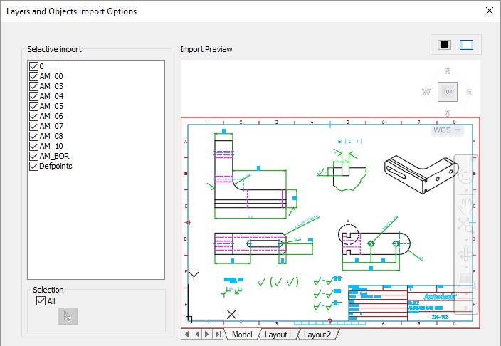
Importing AutoCAD Geometry — AutoCAD geometry can be imported into your sketches. In one case it is imported, add dimensions and constraints every bit if the geometry originated in Inventor.
After selecting the cartoon, specify the layers for import. Optionally, select the objects for import. Finalize the import by specifying the import units, if y'all will apply constraints, and options about converting AutoCAD Blocks to Inventor Blocks.
Re-create and Paste — You tin can re-create and paste straight from AutoCAD into Inventor to bypass the wizard. Using the Windows Clipboard you lot can create copies of your sketch geometry into the aforementioned sketch, into the same model, or even between parts. Use the standard MS Windows functions correct click Copy or <Ctrl> + C and right click Paste or <Ctrl> + V.
Tip: Employ Auto Dimensioning to utilise the "easy" constraints like horizontal, vertical, perpendicular, and parallel.
Utilizing AnyCAD — By utilizing Inventor AnyCAD, associatively import an AutoCAD drawing into your Inventor model. After selecting the cartoon, specify the plane for insertion and the insertion point for the cartoon.
From any sketch use Project DWG Geometry to project in objects from the AutoCAD cartoon equally reference geometry within the sketch. If the AutoCAD drawing changes, this projected geometry automatically updates.
Want more than? Download the full class handout to read on.
Mike Thomas is the technical services manager at Prairie Machine, a mining equipment manufacturer. Reporting to the full general director, he is responsible for overseeing the company's technical operations and the strategic technical growth. He's been using AutoCAD since r13, cutting his solid modeling teeth on Mechanical Desktop, and has been using Inventor since inception.
taylorfroustommer.blogspot.com
Source: https://medium.com/autodesk-university/inventor-sketching-beyond-the-basics-62428ce32315
0 Response to "draw a circle in 3d sketch inventor"
Post a Comment